You must be signed in to read the rest of this article.
Registration on CDEWorld is free. You may also login to CDEWorld with your DentalAegis.com account.
One of the more desirable goals for CAD/CAM restorations is to make them unnoticeable as restorations in the mouth. In popular discourse, CAD/CAM restorations are often portrayed as non-esthetic, unnatural looking, or too similar to temporaries. These criticisms ignore the reality that CAD/CAM restorations can appear to be natural if the clinician devotes a sufficient amount of effort to their creation.1 This article explores a methodology and approach to creating esthetic, successful restorations with CAD/CAM technology in the dental practice, providing specific recommendations for high-quality results. These posterior and anterior recommendations encompass accentuating anatomy after milling on occlusal and buccal surfaces, improving translucency, subtle staining, symmetry, and other factors.
Posterior Recommendations for Enhancing CAD/CAM Restorations
Accentuating Anatomy After Milling
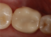
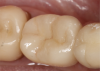
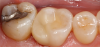
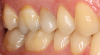
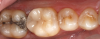
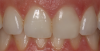
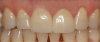
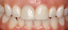
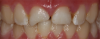
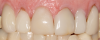
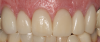
The quality of CAD/CAM restorations is directly correlated with the amount of work dedicated to their manufacture. This principle is exemplified in Figure 1 and Figure 2. The restoration in Figure 2 looks more natural than that in Figure 1. Both restorations are clinically acceptable, featuring sealed margins and functional appearance in the mouth. However, Figure 2 is much more esthetic. Figure 2 has more subtle anatomy, as well as some staining in the grooves that makes the restoration blend in with neighboring teeth. Figure 1 is an example of how CAD/CAM crown restorations appear when they come out of the milling unit. Figure 2 involved the same initial milling process, except with the addition of anatomic accentuation that only took a few minutes to complete with an inverted cone diamond bur. The clinician can simply use the end-cutting bur to scribe anatomy on the occlusal surface of the crown wherever deemed appropriate. Scribing anatomy creates a place for stains to settle after firing, thereby ensuring a more natural look.
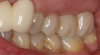
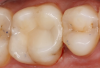
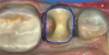
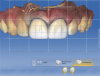
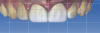
A similar case is shown in Figure 3 and Figure 4, where an onlay was used. Figure 3 shows a scan that was taken on a CAD/CAM system; Figure 4 shows the final restoration bonded in place using an onlay. This was another case where the clinician scribed anatomy, resulting in the appearance of natural stains.
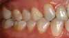
Figure 5 provides further elucidation of this critical finishing step. Most doctors who have encountered this image believe teeth Nos. 13, 14, and 15 are crowns, when in fact they are not. There is actually a bridge, which gives the impression of separate restorations. An appropriate bur for this situation is a fine needle-shaped diamond. After the restoration is milled, the dentist can create anatomy on the buccal surface, define embrasure spaces further, define connector spaces, and then use an endodontic file with some stains, painting them into the interproximal surface of the connectors. This process gives the illusion of separate teeth.
As demonstrated by the prior examples, the first posterior recommendation for making CAD/CAM restorations look natural is to accentuate anatomy on the occlusal and buccal surfaces after the crown is milled. In most instances, the final outcome will be significantly enhanced.
Why Hybrids Are Optimal
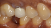
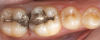
Figure 6 displays a case with a two-surface inlay on an upper first molar. There was a failing amalgam restoration. For the preparation, the amalgam was cleaned up and a two-surface inlay was designed. The clinician used a hybrid material to mill the restoration. The hybrid material blends more easily into the surrounding tooth structure.2 In Figure 6, which depicts the bonded inlay in place, the cavosurface margin between the restoration and tooth surface is mostly hidden.
The image in Figure 7 portrays a case where an onlay was placed on an upper first molar. After the dry fit and bonding in place and polishing, the surface between the restoration and the tooth was barely visible.
How to Improve Translucency
The next recommendation concerns translucency. Figure 8 is for a preparation dubbed a "crownlay," where there was complete cuspal reduction on the tooth. The clinician introduced the axial and made a complete-coverage crown because a significant amount of enamel was present. This enabled the clinician to conserve healthy enamel and achieve the best bond strength on teeth, compared with a complete-coverage crown.3 A block was used for this case that blended in well with neighboring tooth structure; such restorations can be milled very thinly without chipping at the margin.3 From the buccal surface, there was little difference between tooth structure and restoration. After polishing, the result was attractive.
In the case in Figure 9, several crownlays are shown; they are intentionally difficult to recognize. For this case, the clinician placed crownlays on teeth Nos. 3 and 4. The finishing line was above the height of contour. In this type of case, in the author's experience it is best to make a rollercoaster margin and use high-translucency blocks to blend in the restoration.
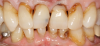
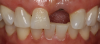
In a case that was completed about 9 years ago, the clinician was not involved with CAD/CAM and used a laboratory-made porcelain-fused-to-metal (PFM) crown on two teeth. The patient returned to the dentist several years later, unhappy with the appearance of the crown (Figure 10). The clinician offered to change the crown at no cost. Although the initial result was clinically acceptable, esthetically it was not exemplary. The dark margin was exposed, the finishing line was above the gum line, and the final shade of the restoration did not match the adjacent teeth. For the new restoration, the clinician used a glass-ceramic crown, although when doing complete-coverage crowns that require blocking a dark stump, low-translucency material is preferred. The clinician also spent time staining and glazing the restoration to more closely mimic neighboring teeth. For posteriors, translucency of material plays a large role in the final outcome. High translucency is preferred for partial coverage and low translucency is preferred for complete-coverage restorations.4-6
Subtle Staining Enhances Esthetic Outcomes
Figure 11 depicts a crown that was placed on tooth No. 4. The preoperative condition of an existing silver amalgam filling with recurrent decay had been visible, so it was converted to a crown. The clinician used some staining and glazing to mimic neighboring teeth. The case in Figure 5 was another example of the power of staining, showing how a bridge can be made to look more natural because of staining placed between the connectors. The clinician stained between teeth Nos. 13 and 14 and between Nos. 14 and 15, as well as along the buccal grooves of the molars.
Figure 12 shows a case where an onlay was placed on tooth No. 30. There was still some healthy tooth structure present on the mesial; the mesial part of the tooth was natural structure and the distal part was the restoration. Figure 13 through Figure 15 show the complete case, the preparation and the design. Some occlusal cavosurface margin was visible. It is clear from these images that doing a small amount of staining and glazing while choosing the right kind of material enabled the clinician to blend the restoration with neighboring teeth. Therefore, the final recommendation for posteriors is that subtle staining can enhance an esthetic outcome.7
Anterior Recommendations for Enhancing CAD/CAM Restorations
Keeping the Midline Straight
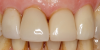
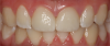
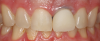
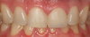
For anteriors, the midline is critical. Figure 16 and Figure 17 show two different cases in which tooth No. 9 was restored. For the case in Figure 16, the clinician placed a veneer on No. 9. For the case in Figure 17, the clinician changed a large composite filling, which was staining and chipping, into a veneer. Figure 17 looks more natural than Figure 16. In Figure 16, the midline was canted, whereas in Figure 17, the midline was straight. With anterior restorations, it is very important not to make a midline canted.8 An analogy would be to compare the Eiffel Tower with the Leaning Tower of Pisa. For anteriors, the most important recommendation is to pay attention to the midline's straightness. Within a CAD/CAM system, a grid can help clinicians set the midline straight.
Achieving Symmetrical Centrals
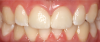
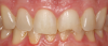
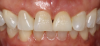
A second recommendation for anteriors relates to the cases shown in Figure 18 and Figure 19. In both cases, the clinician restored teeth Nos. 8 and 9. For the case in Figure 18, veneers were placed on Nos. 8 and 9; for the case in Figure 19, the restoration used crowns on Nos. 8 and 9. Figure 19 looks better esthetically because the centrals in Figure 18 are not symmetrical. For the case in Figure 19, tooth No. 8 was somewhat overlapped onto tooth No. 9, leading to a perfectly symmetrical result. When working on anterior teeth, it is important to make centrals symmetrical.9,10 The case in Figure 19, with a straight midline and symmetrical central, looks esthetically pleasing compared with a case with a canted midline and asymmetry between centrals. Because the centrals were symmetrical, less-optimal aspects of the case went unnoticed. For example, the gingival zenith on tooth No. 11 was pointier than tooth No. 6 and the width of tooth No. 7 was wider than tooth No. 8. These discrepancies were less integral because of the straight midline and symmetrical centrals.
Why Contact-Length-to-Gingival-Height Ratio Matters
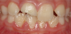
Figure 20 and Figure 21 show another comparison of two cases. In both cases, teeth Nos. 8 and 9 were complete-coverage crowns. Figure 20 is more esthetic than Figure 21. In Figure 20, the lines go from the gingival zenith to the height of the papilla and from the height of the papilla to the contact length. These lengths are relatively equal. As a result, the contact length does not appear too long, whereas with Figure 21, the height of the papilla compared with the length is somewhere around 60:40 or 70:30. The optimal ratio would be 50:50.11,12 The case in Figure 21 was of a long-time patient of the clinician's practice who had orthodontic work performed. She was young and unhappy with discoloration of tooth No. 8. After doing some internal bleaching, she was also unhappy with the overlap of tooth No. 9 over No. 10 and was not willing to endure further orthodontic procedures. She also had root canals on both Nos. 8 and 9. The clinician decided to put crowns on the teeth with a CAD/CAM system. In this case, when the clinician started off, there was a 50/50 ratio, but by the time the case was finished, the ratio was skewed. The clinician made a mistake while designing the crowns: the contact length was closed up slightly more than it should have been, which resulted in the contact length appearing much taller than it was initially.
This mistake can be avoided. In Figure 22, a similar case is presented. The patient had a skiing accident and needed root canals on teeth Nos. 8 and 9. When the clinician was designing the restorations with the CAD/CAM system, an initial scan of the teeth was taken, which gave the final position of the gingiva before any reduction on the teeth or cord packing. The scan showed the clinician the original position of the gingiva. The clinician prepared both teeth for crowns and finished the design (Figure 23). Looking carefully, one can see an open black triangle between Nos. 8 and 9. Most dentists or assistants designing this case would want to close the gap by adding porcelain, but that would be detrimental in the long run because it would create a long contact length.13
Instead, the clinician can use a CAD/CAM system to overlay the original biocopy onto the preparations. In Figure 24, when the original scan taken before preparing the teeth was superimposed over the proposals, it was clear that the final position of the gingiva was actually much higher. The gap was displayed in Figure 23 because of the packed cord on Nos. 8 and 9, as well as the gingiva being pushed back. When the clinician sees that the original position of the gingiva is higher, the clinician can safely assume that after the crowns are placed and bonded, the gingiva will bounce back and close the black triangle.13 The gap can be left open while the clinician transfers to final milling and cementation. Because the height of the gingiva is maintained, the contact does not lengthen. It is important not to blunt the gingiva. During an anterior case, the biocopy should always be scanned so it can be referred to later in the design space. Several factors can be drawn from the biocopy: the height of the gingiva, the emergence profile, the length of the incisal edges, the height of teeth, and other information.14,15
Custom Staining Is Crucial
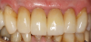
The next recommendation for anteriors is exemplified by a case with a 93-year-old patient. The patient in Figure 25 was unhappy with the appearance of his teeth and insisted that something be done about them the same day as a recall examination. On his upper teeth there was some recurrent decay, failing composite fillings, and overlaps. This type of case usually necessitates a wax-up from the laboratory transferred into the mouth for patient approval, but this patient was in a hurry. The clinician agreed to have the teeth prepared in the morning and then delivered in the evening. Restorations were designed between patients using a grid to make them as symmetrical as possible. When the restorations were milled, there was a shade change between the gingival and the incisal third, but the change was not enough for the clinician to mimic the patient's teeth on the canines. Consequently, the clinician had to do extensive staining, which included different levels of staining for the gingival and incisal third. Four stains were used, with dark orange on the gum line moving to yellow and beige on the body of the restoration. Figure 26 shows the final postoperative image. Because of the recession, the patient had long-looking teeth. The patient also had some dark areas around the gum line. Using the different stains enabled the clinician to mimic the patient's natural teeth. Often, a custom staining job is necessary.
Closely Assess Texture of Neighboring Teeth
Figure 27 shows a pediatric patient who presented with a fractured central incisor, tooth No. 8. This trauma case required a root canal. After the root canal was completed, a dry try-in took place. The restoration was stained, glazed, and bonded, but tooth No. 9 did not display luster-staining and glazing on tooth No. 8 made the restoration look shinier and blend in less well with neighboring teeth. The clinician learned that a good polish was likely needed to keep the restoration matte.
This learning was useful for the case shown in Figure 28. This patient presented with a large composite filling on tooth No. 9 that had failed or fractured. The filling was replaced several times until the patient requested a more permanent restoration; a veneer was chosen. The clinician prepared the case; a dry try-in of the veneer is shown in Figure 29. Dry try-ins are one of the most important parts of an appointment because they are the time when the clinician decides whether to stain and glaze or just polish.16
In this case, the clinician noticed some incisal translucency on the adjacent teeth. However, when the clinician looked at tooth No. 8 and compared it to teeth Nos. 7 and 10, it was clear No. 8 was not very lustrous. It did not have a high-glazed finish compared with the laterals; it had a matte appearance. The clinician decided that an extensive glazing cycle was not needed and instead had the restoration mimic the translucency seen on adjacent teeth. Blue stains were applied on the incisal edge, and the restoration was put through a crystallization process. A glaze was not applied because the clinician did not want to make the restoration too shiny. After the restoration was finished, the clinician tried it in the patient's mouth and began polishing the restoration, checking it every few seconds to know to stop when the facial texture of the veneer matched that of tooth No. 8. Figure 30 shows the final result. Some blue can be seen on the incisal edge because the clinician was trying to mimic the shades on the other teeth. However, there is not a lot of glaze compared with the earlier case.
Figure 31 shows a case where an implant was placed by a periodontist. The patient needed a crown, so the clinician made a custom abutment with a CAD/CAM system. The clinician took a 330 bur and scribed in some of the texturing seen on tooth No. 8 onto tooth No. 9 (Figure 32). The texturing was mimicked by using an articulating paper technique in which the clinician rubbed the articulating paper on both teeth. These cases illustrate the importance of closely assessing neighboring teeth and texture.
Split Larger Cases Into Two Appointments
The patient shown in Figure 33 presented with failing veneers, some of which had open margins, had debonded, or were recemented. There was also recurrent decay and recession, coupled with the patient's unhappiness with the final result. Additionally, there was a crack on the veneer on tooth No. 9. When the clinician took the case, tooth No. 6 had a relatively new crown, but it was decided to remove the veneers on teeth Nos. 7, 8, 9, 10, and 11. The clinician prepared for complete-coverage crowns. Figure 34, featuring the final result, showcases a straightened midline, corrected symmetry of centrals, and even incisal edges. Because the contact length was too long originally, the clinician cleaned up the gingiva and gave it a gradual emergence profile. The gingiva was then able to grow back. Next, the laterals were made to look more natural by ensuring the mesial-line angles of the lateral traveled toward the distal, compared with where the mesial-line angles were too symmetrical. When the clinician tried to mimic the mesial-line angle equally on both No. 7 and No. 10, a triangular-looking lateral resulted. A lateral should look more like a triangle, with the apex going toward the gingiva, versus a thin or thick oval. The inclination of the laterals should also be mesial and lingual; the patient had presented with laterals inclined facially and distally.8
Postoperatively, the incisal embrasure between the centrals was the smallest, the incisal embrasure between the central and the lateral was somewhat larger, and the incisal embrasure between the laterals and the canines was the largest. The embrasures tend to become larger distally; preoperatively, there was no definition of the incisal embrasures in this case.17,18
This case illustrates the final anterior recommendation, which is to split larger cases into two appointments. When clinicians do CAD/CAM restorations on larger cases all in one day, they have to manage the patient and the case simultaneously. Rushing and making mistakes can lead to less-natural results after the case is bonded in place.
Conclusion
Many criticisms of CAD/CAM technology ignore the need for specialization and detail-oriented postfabrication methods. CAD/CAM enhancements are essential to creating a natural, esthetically pleasing outcome. In pursuit of a successful result, clinicians must consider posterior and anterior recommendations for CAD/CAM restorations. Chosen techniques must be case-specific and take into account the patient's preoperative esthetics and desires. The benefits of CAD/CAM, especially when there is a significant amount of attention paid to customization, make it a viable option for many dental practices.
About the Author
Dhaval Patel, DDS
Private Practice
Roseville, California
References
1. Wittneben JG, Gavric J, Belser UC, et al. Esthetic and clinical performance of implant-supported all-ceramic crowns made with prefabricated or CAD/CAM zirconia abutments: a randomized, multicenter clinical trial. J Dent Res. 2017;96(2):163-170.
2. Patel B, Chhabra N, Jain D. Effect of different polishing systems on surface roughness of nano-hybrid composites. J Conserv Dent. 2016;19(1):37-40.
3. Schlichting LH, Resende TH, Reis KR, Magne P. Simplified treatment of severe dental erosion with ultrathin CAD/CAM composite occlusal veneers and anterior bilaminate veneers. J Prosthet Dent. 2016;116(4):474-482.
4. Awad D, Stawarczyk B, Llie N. Translucency of esthetic dental restorative CAD/CAM materials and composite resins with respect to thickness and surface roughness. J Prosthet Dent. 2015;113(6):534-540.
5. Zhang Y, Lawn BR. Novel zirconia materials in dentistry. J Dent Res. 2017 Oct 1 [ePub ahead of print].
6. Zhao M, Sun Y, Zhang J, Zhang Y. Novel translucent and strong submicron alumina ceramics for dental restorations. J Dent Res. 2017 Oct 1. [ePub ahead of print].
7. Rinke S, Fischer C. Range of indications for translucent zirconia modifications: clinical and technical aspects. Quintessence Int. 2013;44(8):557-566.
8. Nold SL, Horvath SD, Stampf S, Blatz MB. Analysis of select facial and dental esthetic parameters. Int J Periodontics Restorative Dent. 2014;34(5):623-629.
9. Ormianer Z, Solodukhin AL, Lauritano D, et al. Bilateral symmetry of anterior maxillary incisors: evaluation of a community-based population. J Biol Regul Homeost Agents. 2017;31(2 Suppl):37-43.
10. Betrine Ribeiro J, Alecrim Figueiredo B, Wilson Machado A. Does the presence of unilateral maxillary incisor edge asymmetries influence the perception of smile esthetics? J Esthet Restor Dent. 2017;29(4):291-297.
11. Fischer KR, Grill E, Jockel-Schneider Y, et al. On the relationship between gingival biotypes and supracrestal gingival height, crown form, and papilla height. Clin Oral Implants Res. 2014;25(8):894-898.
12. Nayak A, Raipoot N, Nayak R, Nayak R. Analysis of morphologic attributes in dental esthetics: a new concept. Int J Periodontics Restorative Dent. 2017;37(6):873-880.
13. Brianezzi LFF, Brondino BM, Chaves GC, et al. Interdental papilla formation after diastema closure. Gen Dent. 2017;65(6):e13-e16.
14. Patel D. CAD/CAM design techniques for predictable anterior restorations. Inside Dentistry. 2015;11(2):62-70.
15. Sannino G, Germano F, Arcuri L, et al. CEREC CAD/CAM chairside system. Oral Implantol (Rome). 2015;7(3):57-70.
16. Brady LA. Anterior veneer try-in. LeeAnnBrady.com. https://leeannbrady.com/esthetic-dentistry/anterior-veneer-try-in. Accessed December 13, 2017.
17. Eduarda Assad Duarte M, Martins Machado R, Fonseca Jardim da Motta A, et al. Morphological simulation of different incisal embrasures: perception of laypersons, orthodontic patients, general dentists, and orthodontists. J Esthet Restor Dent. 2017;29(1):68-78.
18. Foulger TE, Tredwin CJ, Gill DS, Moles DR. The influence of varying maxillary incisal edge embrasure space and interproximal contact area dimensions on perceived smile aesthetics. Br Dent J. 2010;209(3):E4.